Time of Flight Sensors – ToF

Overview
A 3D Time-of-Flight (ToF) camera is a specialized imaging device that captures depth information by measuring the time it takes for a light signal to travel from the camera to an object and back. This technology allows for the creation of three-dimensional images, providing depth data alongside traditional 2D images. The process begins with the ToF camera emitting a light pulse, usually in the infrared spectrum, towards the scene. The light pulse hits objects in the scene and is reflected back towards the camera. A sensor in the camera detects the reflected light, and the time it takes for the light to return is measured very precisely. Based on the speed of light and the time-of-flight measurement, the camera calculates the distance to each point in the scene, creating a depth map.
Key Features
Consumer Electronics: Provides secure and accurate facial identification for unlocking smartphones and tablets
Robotics and Drones: Supplies real-time depth information to navigate safely around obstacles.
Automotive Industry: Supplies real-time depth information to navigate safely around obstacles.
Gaming and Virtual Reality (VR): Enhances safety features such as automatic emergency braking, lane-keeping, and adaptive cruise control with accurate distance measurements.
Industrial Automation: Automates the identification and sorting of items on production lines using detailed 3D data.
Healthcare: Tracks patient movements and activities in real-time, offering valuable data for health monitoring and assistance systems.
Security and Surveillance: Monitors and analyzes crowd density and movement in real-time, enhancing safety and management in public spaces.
- Cost Reduction: Automation reduces operational costs and increases resource utilization.
2D Time-of-Flight vs. 3D Time-of-Flight Cameras
On a broader level time of flight cameras can be divided into two parts which are then subdivided into dToF and iToF, direct and indirect time of flight respectively.
1. 2D Time-of-Flight Cameras
1.1 Functionality: These cameras measure the time it takes for light to reflect off objects and return to the sensor, providing distance measurements at specific points but lacking depth information.
1.2 Applications: Commonly used for tasks such as range finding, speed detection, and basic motion sensing in industrial automation and consumer electronics.
1.3 Advantages: Simple and cost-effective, suitable for applications where detailed 3D mapping is not required.
2. 3D Time-of-Flight Cameras
1.1 Functionality: These cameras capture detailed depth information by measuring the time it takes for light signals to travel to different points on objects and return, creating a comprehensive 3D map of the scene.
1.2 Applications: Essential for advanced tasks like facial recognition, augmented reality (AR), autonomous navigation in robotics, and precise object detection in automotive safety systems.
1.3 Advantages: Provide real-time, precise 3D spatial data, enabling enhanced interaction with the environment and supporting complex applications across industries.
Key Differences
- Depth Capability: While 2D ToF cameras provide distance measurements, 3D ToF cameras deliver full 3D spatial information.
- Complexity and Cost: 2D ToF cameras are simpler and more affordable, whereas 3D ToF cameras are sophisticated and typically more expensive due to their advanced capabilities.
- Applications: 2D ToF cameras excel in basic distance and motion detection tasks, whereas 3D ToF cameras are indispensable for applications demanding detailed spatial awareness and interaction.
- Output: 2D ToF cameras output distance or speed measurements, while 3D ToF cameras produce comprehensive depth maps.
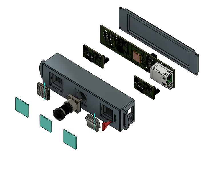
Components of a Time-of-Flight Sensor
- Light Source:
- Type: Usually an infrared (IR) LED or laser diode emitting light pulses.
- Function: Sends out short bursts of light directed towards the target area.
- Optical System:
- Lens: Focuses the emitted light onto the scene for accurate illumination or to form an image.
- Filters: Includes optical filters to refine the wavelengths of light detected by the sensor, ensuring precise measurements.
- Sensor Array:
- Photodetector/Camera Chip: Array of photodiodes or pixels that capture the reflected light.
- Time Measurement Unit: Determines the exact time taken for light to reflect off objects and return.
- Analog Front-End: Amplifies and conditions the detected signals before digital conversion.
- Timing Electronics:
- Time-to-Digital Converter (TDC): Converts analog time measurements into digital signals.
- Clock Generator: Generates precise timing signals for synchronization.
- Signal Processing Unit:
- Digital Signal Processor (DSP) or Microcontroller: Processes digital signals from the TDC to compute distances.
- Depth Calculation Algorithms: Algorithms that transform time-of-flight data into accurate distance or depth values.
- Output Interface:
- Data Output: Provides processed depth information (such as depth maps or point clouds) in digital format for external systems or devices.
Phases in Designing and Implementing Time-of-Flight Sensor
Developing and implementing a 3D Time-of-Flight (ToF) sensor involves several essential phases to ensure its functionality, accuracy, and suitability for specific applications. Here’s a detailed breakdown of the typical process:
- Phase 1: Conceptualization and Requirements Gathering
- Objective Definition: Clearly define the sensor’s goals and requirements, including range, resolution, accuracy, and intended applications (e.g., automotive, consumer electronics).
- Market Analysis: Research existing technologies and competitors to inform design decisions and identify potential innovations.
- Phase 2: System Design
- Component Selection: Choose components such as IR light sources (LEDs or lasers), photodetectors, lenses, and processing units based on performance criteria and cost considerations.
- Optical Design: Design the optical system, including lenses and filters, to optimize light emission, reflection, and detection for precise depth sensing.
- Electronics Design: Develop circuitry for signal processing, timing measurement (TDC), and interfacing with external devices.
- Phase 3: Prototyping
- Proof of Concept: Build a prototype to validate the feasibility of the sensor design and its components.
- Initial Testing: Conduct basic tests to evaluate functionality, performance metrics (e.g., range, resolution), and integration with software algorithms.
- Phase 4: Software and Algorithm Development
- Depth Calculation Algorithms: Create algorithms to process time-of-flight data and generate accurate depth maps or point clouds.
- Signal Processing: Implement digital signal processing techniques to enhance signal quality, minimize noise, and improve distance measurement accuracy.
- Application Integration: Ensure seamless integration with target applications (e.g., robotics, augmented reality) through software development.
- Phase 5: Testing and Validation
- Functional Testing: Conduct comprehensive tests to validate sensor performance across different environments, object materials, and distances.
- Accuracy Verification: Verify depth measurement accuracy against reference standards or ground truth data.
- Reliability Assessment: Evaluate sensor reliability under varying conditions and prolonged use.
- Phase 6: Manufacturing and Production
- Design for Manufacturing (DFM): Optimize the sensor design for mass production, considering factors like cost-effectiveness, scalability, and ease of assembly.
- Quality Control: Establish rigorous quality assurance processes to ensure consistent sensor performance and reliability in manufactured units.
- Phase 7: Deployment and Support
- Documentation: Prepare user manuals, technical documentation, and support materials to assist users and developers in integrating and using the sensor effectively.
- Customer Support: Provide ongoing support, troubleshooting, and maintenance services to ensure customer satisfaction and optimal sensor performance post-deployment.
Conclusion
Designing and implementing a 3D Time-of-Flight sensor requires a methodical approach from initial concept development through to deployment and support. Each phase—from defining requirements and system design to prototyping, algorithm development, testing, manufacturing, and customer support—is crucial for delivering a reliable, high-performance sensor capable of meeting diverse application needs across industries.


